A 1951 Transmitter for the Beginner

***** WARNING *****

***** WARNING *****
Remember this transmitter has 350VDC exposed under the chassis, a common practice before transistors and ICs. Disconnect power before working on it.
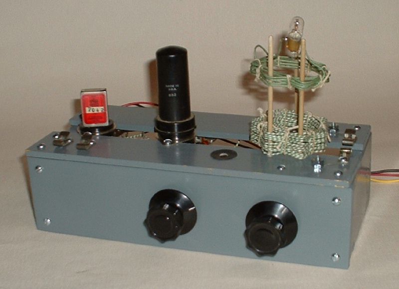
Many times the beginner or novice transmitter of the early 50s was some sort of single tube crystal oscillator running 5 to 10 watts. I chose a 6AG7 crystal controlled oscillator with pi-network output for mine. Plug-in coils or a bandswitch are eliminated by using homemade "basket weave" coils and supporting them on three sucker sticks. Like many beginner low cost rigs, instead of an expensive tuning meter it uses two pilot lights, one to indicate plate current and the other coupled to the pi-network coil to indicate output.
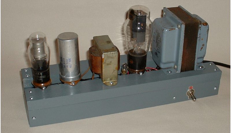
The power supply is fairly straight forward supplying filament voltage and up to 350 volts.
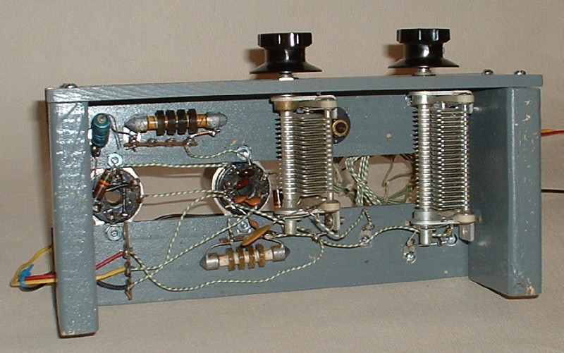
All of the parts of this transmitter (RF and power supply) are mounted on two wooden slat chassis. Many late 40s and early 50s rigs used this construction technique to cut cost and complexity. The slats are spaced properly to allow mounting the tube sockets, transformers and filter capacitor. This works fine as long as shielding is not required. It saved the beginner from buying and using the tools required to bend, cut and hole punch a metal chassis. The wooden slats could even be nailed rather than screwed together to further simplify construction.
In 1951 many beginners painted and dressed up their homebrew, old and military surplus rigs to resemble current "store bought" radios. In 1951 the modern look suggesting reliability and durability included battleship gray, not stained and varnished wood, the finish of the family radio in the living room. In keeping with these times, I chose to paint the rig in battleship gray like much of the commercial equipment in 1951.
Electrically this transmitter is the RF section of "The Lew McCoy Memorial 80/40M Novice Transmitter" by WA6VVL, Electric Radio, July 2008. See also Don Mix's version in May 1951 QST, pg 18 and the original McCoy single tube Novice transmitter in November 1953 QST, pg 28 or any mid 50s ARRL Handbook. See any of these sources for the schematic and parts list.
I used a slat board chassis. See December 1946, pg 33, for an example. For safety I built my transmitter with a wooden front panel. On the front of the transmitter are the plate tuning control on the left and antenna loading control on the right. The key connects to the fanstock clips on the front left while the antenna connects to the fanstock clips on the far right.
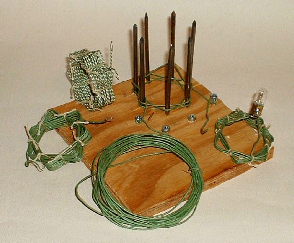
 Coils are wound basket weave style using solid, not stranded, wire. Build a winding form of seven nails evenly spaced around a 2" diameter circle. Winding in and out around the odd number of nails gives the basket weave. Before removing the coil from the winding form, tie it off using string or twine. Support the coils on the transmitter with three round sucked sticks. Two studs at the right rear provide connection points for the pi-network coil...12 turns on 40mtrs and 19 for 80mtrs.
 Position the sockets and coil left to right (from the front) crystal socket, 6AG7 socket, pi-network coil. Insure that there is enough room underneath for the two pi-network tuning capacitors. I oriented the 6AG7 socket so that the key pointed to the back of the transmitter. I used two terminal solder strips to support the RF chokes and a third solder strip for terminating the power cable.
The octal tube socket used for a crystal socket can be wired with
pins 1, 4, 5, 8 shorted together and pins 2, 3, 6, 7 shorted together. This allows a FT 243 crystal to be plugged in to any two pins.
 The power supply supplies filament voltage, 350 volts for the transmitter and regulated 150 volts for either a receiver or transmitter screen grid. The pilot light between the rectifier and the filter serves both as a current "meter" and as a fuse. If the filter capacitor fails, shorting to ground, this bulb will burn out before any damage is done to the transformer.
 Choke input improves high voltage regulation but limits the output voltage. If more voltage is required for a transmitter, the filter should be converted to capacitor input. If this is done, the 5K VR tube dropping resistor may need to be increased in value so that the VR tube is never required to draw more than 40mA.
To minimize harmonic output, this transmitter is designed to only operate on the crystal fundamental frequency. 7 MHz crystals are used on 40 meters and 3.5 MHz crystals are used on 80 meters. The pi-network will load into a variety of antenna lengths. Once an antenna is connected, use the standard pi-network dip-and-load adjustment procedure. Monitor current using either I1 or the lamp/current meter on the power supply. Fine tuning can be done by using the I2 output indicator on top of the pi-network coil. Additional loading capacity, if needed, may be connected across the studs just to the right of the pi-network coil.
QST Magazine, 1915-1969: https://www.worldradiohistory.com/QST.htm
ARRL Handbooks, 1926-1984: https://www.worldradiohistory.com/BOOKSHELF-ARH/Bookshelf_ARRL.htm
Electric Radio, July 2008 "The Lew McCoy Memorial 80/40M Novice Transmitter"