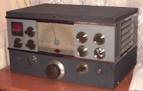
The NC-200 Radio Receiver is a twelve tube superheterodyne covering a continuous frequency range of from 490 to 30,000 kilocycles and band-spreading the 10, 20, 40 and 80 meter amateur bands. It has a number of new features not previously available in any receiver regardless of price. One of these is the stability of the high frequency circuits. A new high frequency oscillator design has been developed in the National laboratories which eliminates the exasperating detuning effect of the R.F. gain control and the even more undesirable motor-boating or fluttering which occurs in most receiver when tuning in strong high frequency signals. Perhaps the best way to prove the exceptional performance of the new circuit is in the 10-meter band where a line voltage shift from 100 to 120 volts produces less than 1000 cycles change in tuning. This is a variation of less than .003 percent. Frequency drift has been reduced to minimum through the use of temperature compensating capacitors not only in the high frequency oscillator circuits but in the R.F. and first detector circuits as well.
FEATURES:
CIRCUIT
The circuit employed on all ranges consists of one stage of radio frequency amplification, a separate first detector and stabilized high frequency oscillator, two intermediate frequency stages, and infinite impedance second detector, a self-balancing phase inverter and audio amplifier, and a push-pull audio output stage. The second detector utilizes one set of elements of a dual triode; the other set of elements is utilized for a series valve noise limiter. Separate tubes are used in the automatic volume control and beat frequency oscillator circuits. The latter is coupled to the second detector for C.W. reception. A crystal filter is connected between the first detector and first I.F. amplifier tubes. All voltages required by the receiver circuits are supplied by a built-in power supply.
| R.F. Amplifier | 6SK7 |
| First Detector | 6K8 |
| H.F. Oscillator | 6J5 |
| First I.F. Amplifier | 6K7 |
| Second I.F. Amplifier | 6SK7 |
| Second Detector-Limiter | 6C8G |
| Automatic Volume Control | 6SJ7 |
| Beat Frequency Oscillator | 6SJ7 |
| Amplifier and Phase Inverter | 6F8G |
| Push-Pull Audio Output(2) | 6V6 |
| Rectifier | 5Y3G |
The master tuning capacitor C-1 and six sets of coils are used to tune the 490 to 30,000 kilocycle range of the receiver. All transformer coils of the R.F. amplifier, first detector and H.F. oscillator stages with their associated padder and air-dielectric trimmer capacitors are mounted in a rigid aluminum casting which slides the length of the chassis, being moved by the MAIN TUNING control. The various coil assembles are fitted with heavy contacts pins which engage spring contacors mounted immediately under the variable tuning capacitor.
CRYSTAL FILTER
Undoubtedly, the most efficient, flexible crystal filter yet designed is used in the NC-200 Receiver. Six uniform steps of selectivity and a variable phasing control allow th receiver to be adjusted to almost any operating condition.
NOISE LIMITER
The noise limiter of the NC-200 Receiver is of the series valve type developed in the National laboratories. Its effectiveness and superior performance as compared to the more common types of "silencers" were proved in the NHU and modernized NC-100 receivers. A threshold control in the front panel permits adjustment of the level at which limiting action starts.
TONE CONTROL
The tone control is used to vary the frequency characteristic of the audio amplifier. The control is particularly helpful when receiving weak signals through interference.
ANTENNA INPUT
Antenna input terminals are located ate the rear of the receiver chassis near the center. The input circuit is suitable for use with a single wire antenna, a balanced feed-line or a low impedance concentric transmission line. Average input impedance is 500 ohms.
AUDIO OUTPUT
Two audio output circuits are provided:
(1) A headphone jack is mounted on the front panel and is wired so as to silence the loud speaker when the phone plug is inserted. The correct load impedance for the headphone output is 20,000 ohms.
(2) A five prong speaker socket (X-1) is provided at the rear of the receiver chassis to this socket are brought the audio output leads. The proper load impedance (total) for the output circuit is 10,000 ohms.
PICK-UP JACK
A pick-up jack mounted on the front panel of the Receiver may be used to connect auxiliary apparatus, such as a phonograph pick-up, to the audio system of the NC-200 Radio Receiver. This input circuit is high impedance and feeds into the 6F8G Audio Amplifier-Phase Inverter tube. The TONE and AF GAIN controls are operative with this connection.
Amateur Net Price $147.50 with speaker, ready to run.
Source: Instruction Manual for The National NC-200 Series Universal Communications Receivers, Photo from Richard Post
Back to the National Product Line